
Spatial Design & Visualization
As an industrial designer, I was responsible for developing the general layout, detailed blueprints, and comprehensive 3D models for several water treatment plants that utilize Krofta Dissolved Air Flotation (DAF) technology. The design optimized spatial efficiency, workflow, and accessibility while ensuring compliance with industry standards. Key functional zones, including filtration, chemical treatment, and storage, were seamlessly integrated to enhance operational performance. The 3D models provided stakeholders with a clear visualization of the plant’s structure, facilitating informed decision-making during the planning phase.

Slaughterhouse Water Treatment Plant – This facility, designed from my blueprints, features underground water tanks with submerged pumps for efficient wastewater treatment. Elevated structures house sedimentation and filtration systems, ensuring proper organic waste management. The design balances functionality for livestock with effective water treatment, demonstrating the successful transition from concept to reality.

Krofta Supracell DAF – This 3D model of a Krofta Supracell Dissolved Air Flotation (DAF) system was created while working for BioDAF Water Technology. The model serves as a visual aid to demonstrate the machinery’s operation and spatial requirements to clients. The rendering showcases a high level of detail, including the flotation tank, rotating skimmer arm, and essential components responsible for separating suspended solids from water. The use of realistic materials, reflections, and fluid dynamics enhances its accuracy, making it a valuable tool for presentations, technical discussions, and facility planning.
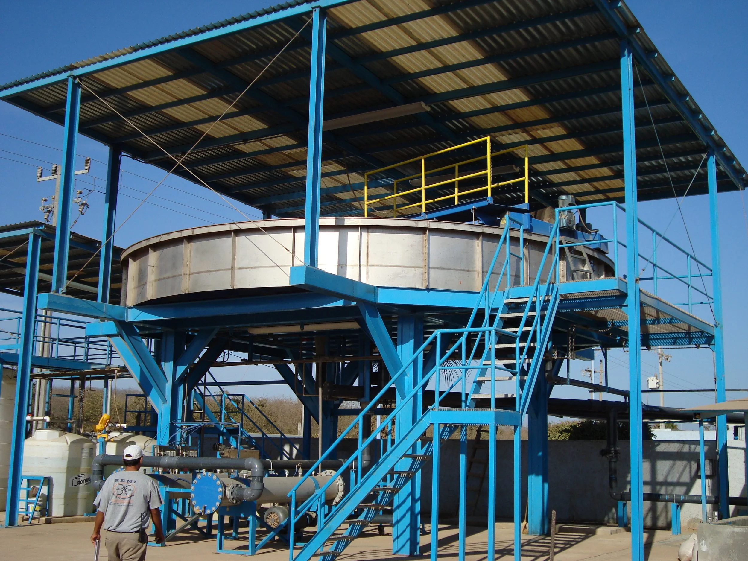
Krofta Supracell DAF – This image presents the completed installation of a Krofta Supracell Dissolved Air Flotation (DAF) system, based on the detailed blueprints I developed. The final structure features an elevated steel framework, designed for optimal space efficiency and maintenance access. The circular flotation tank, central to the system, operates with an integrated skimming mechanism to remove suspended solids and contaminants, ensuring high-efficiency water clarification. Supporting components, including chemical dosing units and pressurized air systems, align with the planned design, ensuring seamless operation. This project exemplifies the transition from concept to reality, showcasing the effectiveness of precise engineering and 3D modeling in the execution of complex water treatment solutions.
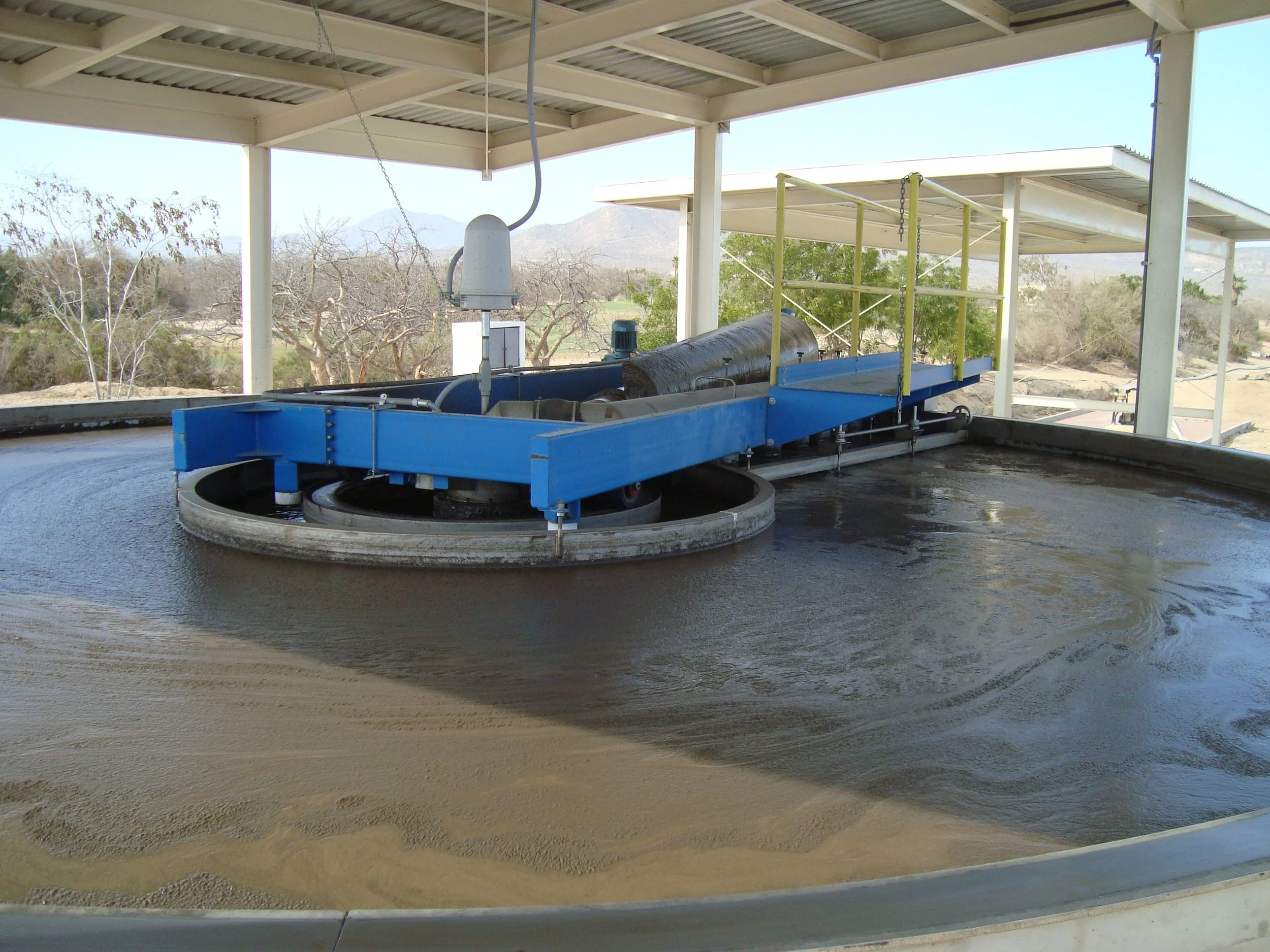
This close-up highlights the Dissolved Air Flotation (DAF) unit in action, showcasing its efficiency in separating solids from wastewater. It’s a key component of the treatment process, ensuring high-performance clarification as designed in my blueprints.

Portable Water Treatment Plant – 3D Model This 3D model showcases a fully integrated portable water treatment plant designed to fit within a 40-foot shipping container. Developed while working for BioDAF Water Technology, this system provides a compact and efficient solution for remote or temporary water treatment needs. The model features a highly detailed representation of key components, including a dissolved air flotation (DAF) unit, filtration system, chemical dosing equipment, and control panel. The realistic rendering highlights the optimized spatial arrangement, facilitating easy transportation, installation, and operation. This visualization serves as an essential tool for client presentations and project planning.

Portable Water Treatment Plant Engineering Blueprint – This technical drawing provides a detailed layout of a 40-foot high-cube containerized water treatment plant. Designed while working for BioDAF Water Technology, this blueprint outlines the spatial arrangement of key components, including the dissolved air flotation (DAF) clarifier, chemical dosing system, filtration units, ozone treatment, and control panels. The plan ensures optimal workflow, accessibility, and operational efficiency while maintaining a compact footprint for easy transport and deployment. This blueprint serves as a crucial reference for manufacturing, installation, and client consultation.
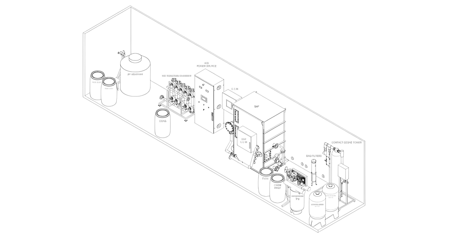
Portable Water Treatment Plant Engineering Blueprint – Isometric technical drawing of the 40-foot high-cube containerized water treatment plant.

This is a process flow diagram for a water treatment system, incorporating key components such as a DAF clarifier, biological reactor, sludge handling, and chemical dosing. It represents the finalized design from my blueprints, ensuring efficient wastewater treatment and reuse. Let me know if you need any modifications or explanations!
Xcaret Water Treatment Plant – This wastewater treatment plant at Xcaret Park ensures efficient water reuse through a flow regulation tank, biological reactor, and Supracell SPC-18 DAF system. Chemical dosing and chlorine contact tanks provide final disinfection, while a sludge dewatering system optimizes waste management, supporting Xcaret’s sustainability goals.